
Comprehensive Introduction of Fiber Optic Splitter
Fiber splitter contains multiple input and output ends. Whenever the light transmission in a network needs to be divided, fiber optic splitter can be implemented for the convenience of network interconnections. This article will help you to gain more knowledge of optical fiber splitter manufacturing, fiber splitter test, and fiber splitter applications.
What is Fiber Optic Splitter
Fiber optic splitters are essential components in optical communication networks. These passive devices split an input optical signal into two or more output paths, allowing the signal to be transmitted to different terminals. Splitters optimize fiber utilization, eliminating the need for dedicated cables for each terminal.
There are two main types of fiber optic splitters based on manufacturing techniques: Planar Lightwave Circuit (PLC) splitters and Fused Biconical Taper (FBT) splitters.
PLC Splitters
PLC splitters provide an even distribution of optical signals, better performance, and wider bandwidth, making them ideal for large networks or applications requiring higher split ratios. It's important to note that with the widespread use of PLC splitters, uniform split ratios may not always meet specific resource allocation needs. Therefore, unbalanced PLC splitters are gradually entering the market. For example, the FS 1x5 unbalanced PLC splitter can distribute the input optical signal to CH1 at ratios of 20%, 33%, 50%, 75%, or 95%, with the remaining optical power evenly distributed among the other four channels (CH2-CH5).

Figure 1: 1x5 unbalanced PLC splitter
Additionally, FS offers six different packaging options for PLC splitters: bare PLC splitter, blockless PLC splitter, ABS PLC splitter, LGX box PLC splitter, FHD Box PLC splitter, and 1U Rack Mount PLC splitter. Users can choose different types of PLC splitters based on their specific application needs.
For more details: How Many Fiber Optic Splitter Types Are There?
FBT Splitters
FBT splitters are made by fusing and tapering multiple fibers together, creating the splitting effect. The split ratio of FBT splitters is customizable and cost-effective, making them suitable for small-scale applications. In contrast, PLC splitters use waveguides and thin-film filters to separate optical signals.
For more information, you can check: FBT Splitter vs. PLC Splitter: What Are the Differences?
How to Manufacture a Fiber Optic Splitter?
In all, there are five steps to manufacture a passive optical splitter. Each step requires strict control and management of various parameters like environment, temperature, and detailed precision on assembly and equipment. We will now provide a detailed introduction using PLC splitters as an example.
Step One: Components Preparation
The three main components of a passive optical splitter are the input and output fiber arrays and the chip. The design and assembly of these are the keys to producing a high-quality PLC splitter. The PLC circuit chip is embedded on a piece of glass wafer, and each end of the glass wafer is polished to ensure highly precise flat surface and high purity. The v-grooves are then grinded onto a glass substrate. A single fiber or multiple ribbon fiber is assembled onto the glass substrate. This assembly is then polished.

Figure 2: Main Components of a Passive Optical Splitter
Step Two: Alignment
After the preparation of the three components, they are set onto an aligner stage. The input and output fiber array is set on a goniometer stage to align with the PLC chip. Physical alignment between the fiber arrays and the chip is monitored through a continuous power level output from the fiber array.
Step Three: Cure
The assembly is then placed in a UV (ultraviolet) chamber where it will be fully cured at a controlled temperature.
Step Four: Packaging
The bare splitter is aligned and assembled into a metal housing where fiber boots are set on both ends of the assembly. And then a temperature cycling test is needed to ensure the final product condition.
Step Five: Optical Testing
In terms of testing, three important parameters such as insertion loss, uniformity and polarization dependent loss (PDL) are performed on the splitter to ensure compliance to the optical parameters of the manufactured splitter in accordance with the GR-1209 CORE specification.
How to Test the Quality of Fiber Optic Splitter?
The quality of a fiber optic splitter is mainly determined by five specifications, namely optical bandpass, insertion loss, return loss, uniformity, and directivity. The following part outlines how to test each specification.
-
The optical bandpass can be tested by connecting the optical splitter to an optical spectrum analyzer with a high-powered light source having a central wavelength of the required bandpass. The attenuation across the required bandpass shall meet the splitter requirements.
-
The insertion loss is tested by using a light source and power meter. The reference power level is obtained and each output port of the optical splitter is measured.
-
The return loss is tested by using a return loss meter. The input port of the splitter is connected to the return loss meter and all the output ports are connected to a non-reflective index matching gel.
-
The uniformity of the optical splitter can be determined by referring to the results from the insertion loss test to ensure that the difference between the highest loss and the lowest loss is within the acceptable uniformity value.
-
Directivity can be measured in a manner similar to the insertion loss test. However, the light source and power meter are connected to each of the input ports and two output ports.
How to Apply Fiber Optic Splitters In PON System?
Fiber optic splitters, enabling the signal on the optical fiber to be distributed between two or more optical fibers with different separation configurations (1×N or M×N), have been widely used in PON networks. FTTH is one of the common application scenarios. A typical FTTH architecture is: Optical Line Terminal (OLT) located in the central office; Optical Network Unit (ONU) situated at the user end; Optical Distribution Network (ODN) settled between the previous two. An optical splitter is often used in the ODN to help multiple end-users share a PON interface.

Figure 3: Fiber Optic Splitter Application in PON
Point-to-multipoint FTTH network deployment can be further divided into the centralized (single-stage) or cascaded (multi-stage) splitter configurations in the distribution portion of the FTTH network. The centralized splitter uses single-stage splitter located in a central office in a star topology. The cascading splitter approach uses multi-layer fiber splitters in a point to multi-point topology.
Fiber Optic Splitter In Centralized PON Architecture
The centralized architecture generally uses 1×32 splitters in the central office located anywhere in the network. The splitter input port is directly connected via a single fiber to a GPON/GEPON optical line terminal (OLT) in the central office. On the other side of the splitter, 32 fibers are routed through distribution panels, splice ports and/or access point connectors to 32 customers’ homes, where it is connected to an optical network terminal (ONT). Thus, the PON network connects one OLT port to 32 ONTs.
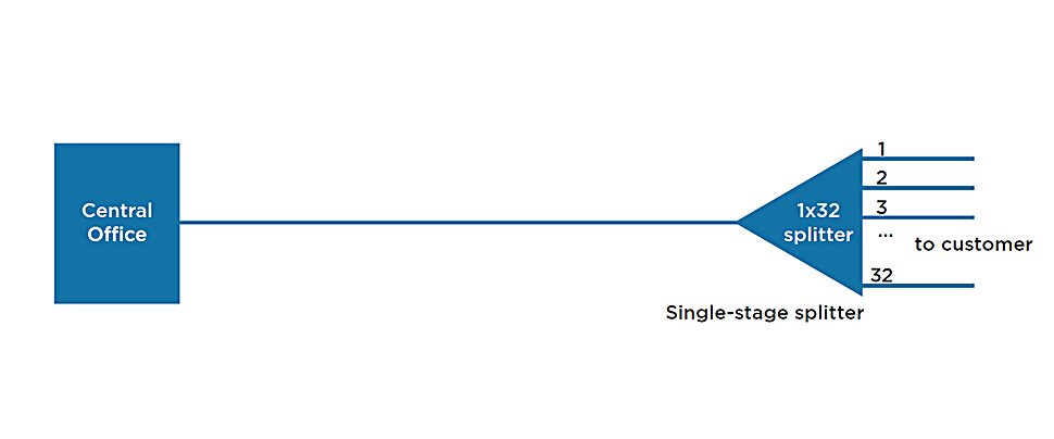
Figure 4: Fiber optic splitter in centralized PON architecture
Fiber Optic Splitter In Cascaded PON Architecture
A cascaded architecture may use a 1×4/1×8 fiber splitter residing in an outside plant enclosure/terminal box. This is directly connected to an OLT port in the central office. Each of the four fibers leaving this stage 1 splitter is routed to an access terminal that houses a 1×8/1×4, stage 2 splitter. In this scenario, there would be a total of 32 fibers (4×8) reaching 32 homes. It is possible to have more than two splitting stages in a cascaded system, and the overall split ratio may vary (1×16 = 4 x 4, 1×32 = 4 x 8, 1×64 = 4 x 16, 1×64 = 8 x 8).
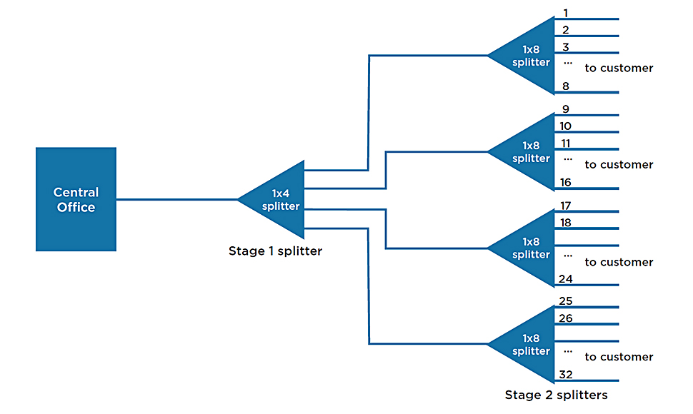
Figure 5: Fiber optic splitter in cascaded PON architecture
Conclusion
Fiber optic splitters enable a signal on an optical fiber to be distributed among two or more fibers. Since fiber splitters contain no electronics nor require power, they are an integral component and widely used in most fiber optic networks. Thus, choosing fiber optic splitters to help increase the efficient use of optical infrastructure is key to developing a network architecture that will last well into the future.
FS has a professional product and technical team that can provide you with customized, high-quality solution services. If you have any questions about fiber splitters or need expert assistance in selecting the right products or building your network, please feel free to contact us.


Email Address


PoE vs PoE+ vs PoE++ Switch: How to Choose?
May 30, 2024


-