
A Closer Look at Mux and Demux: Applications and Key Parameters
WDM (Wavelength Division Multiplexing) mux and demux are devices used in optical communication systems to combine and separate multiple optical signals of different wavelengths, respectively. They are key equipment in WDM systems, allowing for the transmission of multiple signals simultaneously over a single optical fiber. In this article, we will explore what wdm mux and demux are, as well as discuss their applications and key parameters that determine their performance.
What Is WDM Mux and Demux?
A WDM mux and demux, also known as a WDM multiplexer and demultiplexer, is a device that combines multiple optical signals of different wavelengths onto a single optical fiber for transmission. It takes several input signals, each operating at a specific wavelength, and combines them into a composite signal using different techniques such as arrayed waveguide gratings (AWGs) or thin-film filters (TFF). The combined signal is then transmitted over a single fiber simultaneously to the receiving end, increasing the capacity and efficiency of the optical communication system.

Figure1. Introduction of WDM Mux and Demux
Mux and Demux Applications
Optical Communication Network
Fiber optic Mux and Demux enhances optical communication networks by increasing transmission capacity, enabling long-distance communication, and providing network topology flexibility. Using multiplexers and demultiplexers, multiple signals can be transmitted on the same fiber, maximizing bandwidth to meet growing needs. They extend signal transmission distances through WDM and DWDM, supporting long-distance communications like backbone networks and submarine cables. Additionally, they allow cross-connections between different fiber links, improving signal routing and network management efficiency.
Data Center
Fiber optic Mux and Demux is widely used in data centers to improve bandwidth utilization and data transmission efficiency. It enables high-density data transmission by combining multiple optical signals into a single signal, thereby increasing the overall bandwidth of the data center. Additionally, it facilitates fast data exchange by allocating different data traffic to separate fiber channels for parallel transmission, enhancing the speed and efficiency of data exchanges between servers and storage devices. As data centers expand and business needs grow, fiber optic Mux and Demux supports network expansion and upgrades by increasing the number of fiber channels or utilizing tighter wavelength spacing to accommodate rising data demands.
Mux and Demux Key Performance Parameters
Multiplexer and demultiplexer are fundamental components in digital systems that enable efficient data transmission and control. Commonly there are two types: cwdm mux demux and dwdm mux demux. Some wdm multiplexer and demultiplexer devices have both multiplexing and demultiplexing functions, and some devices only support multiplexing or demultiplexing functions. Their main parameters determine the performance and effectiveness in various applications, including operating wavelength, insertion loss, isolation, channel spacing, PDL (Polarization Dependent Loss), channel passband, directivity, etc,. Understanding these parameters is crucial for designing and implementing robust and efficient digital systems.
Operating Wavelength
WDM multiplexer and demultiplexer operate based on the principle of transmitting multiple signals over different wavelengths of light. The operating wavelength refers to the specific wavelength range at which the mux and demux is designed to function. Common operating wavelengths include the C-band (around 1550 nm) and the L-band (around 1570 nm to 1620 nm). The choice of operating wavelength depends on the specific application and compatibility with the optical network.
Channel Spacing
Channel spacing refers to the separation between adjacent wavelengths in a WDM system. It determines the number of channels that can be transmitted over the available bandwidth. The most common channel spacing values are 50 GHz and 100 GHz, corresponding to approximately 0.4 nm and 0.8 nm, respectively. Narrower channel spacing allows for higher channel density but may increase the complexity and cost of the system.
Insertion Loss
Insertion loss is the reduction in optical power that occurs when the signal passes through the mux and demux. It is caused by various factors, including fiber coupling, connectors, and the internal components of the mux and demux itself. Low insertion loss is desirable to minimize signal degradation and ensure efficient transmission. It is typically specified in decibels (dB), with lower values indicating better performance.
Isolation
Isolation refers to the degree of separation between adjacent channels in a WDM system. It measures the ability of the multiplexer and demultiplexer to prevent signal crosstalk between channels. High isolation is crucial to maintain signal integrity and minimize interference. It is also specified in decibels (dB), with higher values indicating better isolation.
PDL (Polarization Dependent Loss)
PDL is a measure of the variation in insertion loss that occurs with changes in the polarization state of the input signal. It is caused by the inherent birefringence of optical components and can lead to signal distortion and power fluctuations. Low PDL is desirable to ensure consistent performance regardless of the polarization state of the input signal.
Channel Passband
The channel passband represents the range of wavelengths over which the multiplexer and demultiplexer allows the transmission of signals. It is typically specified as the full width at half maximum and indicates the bandwidth available for each channel. A wide channel passband allows for the transmission of broader spectra, enabling higher data rates.
Directivity
Directivity refers to the ability of the multiplexer and demultiplexer to distinguish between the desired input/output channel and unwanted signals or reflections. It measures the ratio of power transmitted to the desired channel compared to the power coupled to other channels or reflected back. Higher directivity indicates better performance and minimizes signal loss.
Crosstalk
Crosstalk is the unwanted coupling of signals between different channels in a WDM system. It can occur due to imperfections in the mux and demux or external factors such as fiber bending or splicing. Low crosstalk is essential to maintain signal integrity and prevent interference between channels.
Reliability
Reliability is a crucial parameter for any electronic component. Mux and demux should be designed to operate reliably over extended periods, with minimal degradation in performance. Factors such as environmental conditions, temperature stability, and component quality contribute to the overall reliability of the mux and demux.
Conclusion
Understanding applications and parameters of Mux and Demux is essential when selecting and designing them. Each parameter has its own trade-offs, and the optimal choices depend on the requirements and constraints of the system. By considering these parameters, engineers can ensure the efficient and reliable operation of WDM multiplexer and demultiplexer in high-capacity optical networks. At FS, we offer a comprehensive selection of WDM Mux and Demux products tailored to meet your specific requirements. Our extensive product range includes CWDM Mux and Demux as well as DWDM Mux and Demux . FS provides a variety of customizable options, allowing you to choose products based on your exact needs. You can select between single-fiber or dual-fiber configurations, different wavelengths, varying numbers of channels, diverse sizes, and various port types. Additionally, you have the flexibility to choose the channel spacing that best fits your network infrastructure.


Email Address


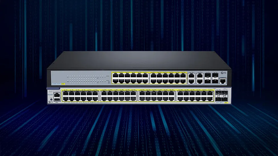
PoE vs PoE+ vs PoE++ Switch: How to Choose?
May 30, 2024


-