Optical Power Meter (OPM): A Must for Fiber Cable Testing
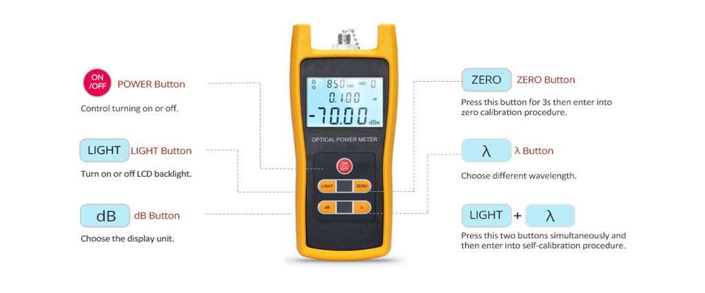
An optical power meter (OPM), also called optical power meter tester or OPM tester, is a testing instrument working to accurately measure the power of fiber optic equipment, or the power of an optical signal passed through the fiber cable. Made up of a calibrated sensor that measures an amplifier circuit and a display, the OPM tester can be used for installation, debugging, and maintenance of any fiber network. And it can adapt to a variety of connector styles such as SC, ST, FC, etc. Generally, there are five buttons on the optical power meter: POWER button, LIGHT button, dB button, ZERO button and λ button. The functions of each button are shown below:

The optical power meter reading expressed in units of dBm on the OPM screen is an intuitional way to measure optical power. The “m” in dBm refers to the reference power which is 1 milliwatt. Thus a source with a power level of 0 dBm has a power of 1 milliwatt. Likewise, -10 dBm is 0.1 milliwatt and +10 dBm is 10 milliwatts. The more negative a number is, the higher the loss. Although OPM testers measure a negative number for loss, it is conventionally said as a positive number. For example, if the optical power meter reading is “-3.0 dB”, the loss is 3.0 dB. In addition, optical power ranges differ from each other due to network types. The table below shows the differences in several typical fiber optic communication systems.
| Network Type | Wavelength (nm) | Power Range (dBm) | Power Range (W) |
|---|---|---|---|
| Telecom | 1310, 1550 | +3 to -45 dBm | 50 nW to 2 mW |
| Datacom | 650, 850, 1300 | 0 to -30 dBm | 1 to 100 uW |
| CATV, DWDM | 1310,1550 | +20 to -6 dBm | 250 uW to 10 mW |
Types of Optical Power Meter
There are various OPM testers due to different resolutions varying from 0.001dB to 0.1dB. One should choose an appropriate resolution for measurement according to the test need. For example, laboratory networks usually need OPM testers with a resolution of 0.01dB, and a resolution of 0.001dB is available on a few specialized fiber optic power meters.
In addition, the measurement uncertainty of practically all fiber optic power meters is the same, limited by the physical constraints of transferring standards with optical connectors. Most meters have an uncertainty of +/-5% or approximately 0.2dB, no matter what the resolution of the display may be.
Fiber Optic Power Meter Test Procedure
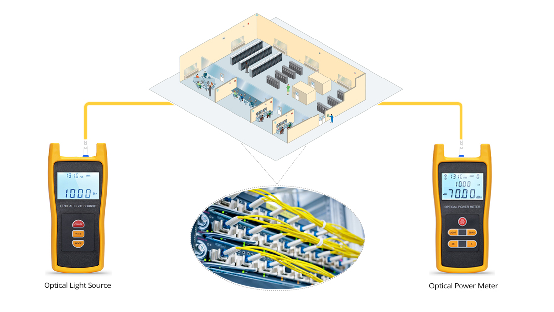
To test the end-to-end performance of a fiber optic system, two pieces of handheld equipment are needed – an OPM tester and a light source. The light source sends a wavelength of light down the fiber. At the other end of the cable, the power meter reads that light, or optical power level, and determines the amount of signal loss. Since optical fiber loss varies with wavelength, optical power meters should use the same wavelength as the one used by the light source. For example, if the light source operates at the 1310nm wavelength, the optical power meter should also be set to 1310nm testing.

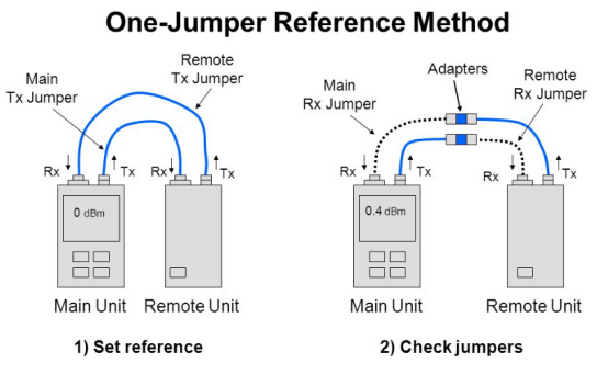
Power meter and light source testing, also known as the one jumper method, is the most accurate way to measure end-to-end signal loss of the fiber, referred to as attenuation. Listed below are TIA/EIA-568 insertion loss limits for the various components. Specific installations or protocols may impose stricter limits.
Loss budget (TIA/EIA specification limits)
| Element | Insertion Loss |
|---|---|
| Splice | < 0.3 dB at all wavelengths |
| Connector Pair | < 0.75 dB at all wavelengths |
Test results should be compared to the link attenuation allowance calculated as follows:
Link Attenuation Allowance (dB) = Cable Attenuation Allowance (dB) + Connector Insertion Loss Allowance (dB) + Splice Insertion Loss Allowance (dB)

Then, how to operate the optical power meter and optical light source? The video below gives you a clear fiber optic power meter test procedure and will show how to test fiber insertion loss with the two fiber optic testers.
You might be interested in
Email Address

-
PoE vs PoE+ vs PoE++ Switch: How to Choose?
Mar 16, 2023


