- English
- German
- French
- Spanish
- Japanese
- Italian
- Chinese
- Chinese (traditional)
- Home
- Blog
- Case Study
- Knowledge Center
- Encyclopedia
- Story
- Video
- Blog Type
- Product
- Topic
- Region
Hot Search
- Product Updates
- Share FS
- PoE Switch
- Networking
- Networking Devices
- Home
- Blog
- Case Study
- Knowledge Center
- Encyclopedia
- Story
- Video
-
- Home
- Blog
- Case Study
- Knowledge Center
- Encyclopedia
- Story
- Video
- Blog Type
- Product
- Topic
- Region
- Home
- Blog
- Case Study
- Knowledge Center
- Encyclopedia
- Story
- Video
- English

Hot Search
- Product Updates
- Share FS
- PoE Switch
- Networking
- Networking Devices
 Driving Next Generation Data Centers Toward 400G
Optical Time-Domain Reflectometer Tutorial
Optical Time-Domain Reflectometer Tutorial
What Is OTDR?
Optical Time-Domain Reflectometer (OTDR) is an optoelectronic instrument used to characterize an optical fiber. It can be considered as the optical equivalent of an electronic time-domain reflectometer.
OTDR injects a series of optical pulses into the fiber under test. It also extracts, from the same end of the fiber,light that is scattered or reflected back from points along the fiber. The strength of the return pulses is measured and integrated as a function of time, and is plotted as a function of fiber length.
It may be used for estimating the fiber length and overall attenuation, including splice and mated-connector losses. It may also be used to locate faults, such as breaks, and to measure optical return loss. To measure the attenuation of multiple fibers, it is advisable to test from each end and then average the results, however this considerable extra work is contrary to the common claim that testing can be performed from only one end of the fiber.
In addition to required specialized optics and electronics, OTDRs have significant computing ability and a graphical display, so they may provide significant test automation. However, proper instrument operation and interpretation of an OTDR trace still requires special technical training and experience.
How Does an OTDR Work?
OTDR fiber tester works indirectly by using a unique phenomena of fiber to imply loss, unlike fiber optic light sources and power meters which measure the loss of the fiber optic cable plant directly by duplicating the transmitter and receiver of the fiber optic transmission links. It works like a radar. It first to send a signal for optical fiber, and then observe what return from one point to the information. This process will be repeated, then the results were averaged and to be displayed in the form of track, the track is described within the whole period of optical fiber (or the state) of the fiber on the strength of the signal.
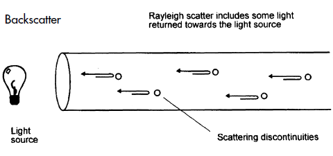
As light travels along the fiber, a small proportion of it is lost by Rayleigh scattering. Rayleigh scattering is caused by the irregular scattering signal along the fiber produced. Given fiber optic transceiver parameters, the Rayleigh scattering power can be marked out. If the wavelength is known, it is proportional to the signal of pulse width, the longer backscattering, the stronger power. Rayleigh scattering power is related to the wavelength of emission signal, the shorter wavelength, the stronger power. That is to say, 1310nm signal path of the Rayleigh backscattering is higher than 1550 nm Rayleigh backscattering.
OTDR uses Rayleigh scattering to represent the characteristics of fiber optic. OTDR measurements back to part of scattering light to the OTDR port. As the light is scattered in all directions, some of it just happens to return back along the fiber towards the light source. This returned light is called backscatter as shown below.
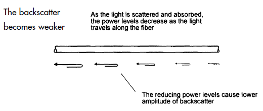
The backscatter power is a fixed proportion of the incoming power and as the losses take their toll on the incoming power, the returned power also diminishes as shown in the figure.
OTDR uses the backscattered light to make its measurements. It sends out a very high power pulse and measures the light coming back. It can continuously measure the returned power level and hence deduce the losses encountered on the fiber.
Any additional losses such as connectors and fusion splices have the effect of suddenly reducing the transmitted power on the fiber and hence causing a corresponding change in backscatter power. The position and degree of the losses can be ascertained. At any point in time, the light the OTDR sees is the light scattered from the pulse passing through a region of the fiber.
Think of the OTDR pulse as being a virtual source that is testing all the fiber between itself and the OTDR as it moves down the fiber.Since it is possible to calibrate the speed of the pulse as it passes down the fiber, the OTDR can correlate what it sees in backscattered light with an actual location in the fiber. Thus it can create a display of the amount of backscattered light at any point in the fiber.
There are some calculations involved. Remember the light has to go out and come back, so you have to factor that into the time calculations, cutting the time in half and the loss calculations, since the light sees loss both ways. The power loss is a logarithmic function, so the power is measured in dB.
The amount of light scattered back to the OTDR is proportional to the backscatter of the fiber, peak power of the OTDR test pulse and the length of the pulse sent out. If you need more backscattered light to get good measurements, you can increase the pulse peak power or pulse width as shown in the picture.
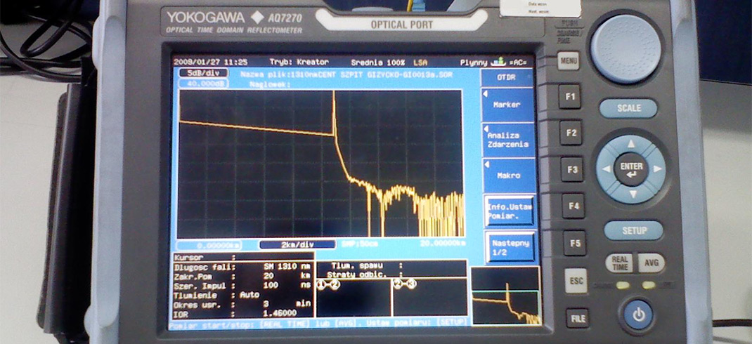
Some events like connectors show a big pulse above the backscatter trace. That is a reflection from a connector, splice or the end of the fiber. They can be used to mark distances or even calculate the back reflection of connectors or splices, another parameter we want to test in single mode systems.
OTDRs are generally used for testing with a launch cable and may use a receive cable. The launch cable allows the OTDR to settle down after the test pulse is sent into the fiber and provides a reference connector for the first connector on the cable under test to determine its loss. A receive cable may be used on the far end to allow measurements of the connector on the end of the cable under test also.
When Do We Use an OTDR?
Since OTDRs are very expensive and have only specific uses, the decision to buy one must be made carefully. It is very important to understand when we need an OTDR and when it is not appropriate.
If we are installing an outside plant network such as a long distance network or a long campus LAN with splices between cables, we will need an OTDR to check if the fibers and splices are good. The OTDR can see the splice after it is made and confirm it's performance. It can also find stress problems in the cables caused by improper handling during installation. If we are doing restoration after a cable cut, the OTDRs will help find the location of cut and help confirm the quality of temporary and permanent splices to restore operation. On single mode fibers where connector reflections are a concern, the OTDRs will pinpoint bad connectors easily.
OTDRs should not be used to measure cable plant loss although some have this function. That is the job of the source and power meter. The loss measured will not correlate between the two methods and the OTDR cannot show the actual cable plant loss that the system will see.
What's more, the limited distance resolution of the OTDR makes it very hard to use in a LAN or building environment, where cables are usually only a few hundred feet long. The OTDR has a great deal of difficulty resolving features in the short cables of a LAN and is more often than not simply confusing to the user.
How to Choose the Right OTDR?
An OTDR is the best option if you want to know the length of the fiber or obtain performance data of the optical links, as it can get events such as the attenuation of a connector, coupler loss or joints along optical network being measured. However, OTDRs are very expensive so that we should know how to choose a right one.
The choice of an OTDR is based on a relatively simple guideline: determining precise wavelengths (850/1300nm for multimode fiber, while 1310/1550nm for single mode fiber), establish the dynamic range necessary based of distance to cover and select equipment with smaller dead zone.
Nowadays, there are a lot of OTDRs of different models available on the market, but these are complex devices and fiber optic testing, by the fact that its characteristics and capabilities vary widely, can be a problem to decide the tool test is best for each installation.
When selecting OTDRs, we must think about some functionality such as dynamic range, dead zones (attenuation and event), sampling resolution, ability to set thresholds for pass/fail, post-processing and reporting, etc.
Dynamic Range
This specification determines the total optical loss that the OTDR can analyze, and the total length of the fiber link can measure unit. The higher the dynamic range, the greater the distance the OTDR can analyze. The specification of the dynamic range must be carefully considered for two reasons as below.
1. OTDR manufacturers specify the dynamic range of ways (playing with specifications as pulse amplitude, signal-to-noise ratio, averaging time, etc.). It is therefore important to understand them thoroughly and avoid making comparisons unsuitable.
2. Having an insufficient dynamic range results in an inability to measure the full link length, affecting, in many cases, the precision of the link loss and connector losses and attenuation far end . A good method is to select an OTDR empirical whose dynamic range is 5 to 8dB higher than the maximum loss you will find.
For example, a single mode OTDR with a dynamic range of 35dB has a useable dynamic range of about 30 dB. Assuming a normal fiber attenuation of 0.20dB/km at 1550nm and splices every 2km (0.1dB loss per splice), a unit like this can accurately certify distances up to 120km.
In comparison, a single-mode OTDR with a dynamic range of 26dB has a usable dynamic range of about 21dB. Assuming an ordinary attenuation of 0.5dB/km at 1300nm and two connector loss around 1dB each, this unit may accurately certify distances up to 38km.
Dead zones
TDead zones originate from reflection events (connectors, mechanical splices, etc.). Along the link, affecting the ability to accurately measure OTDR attenuation smaller links differentiate closely spaced events as for example patch panel connectors, etc.
When the strong optical reflection of the event reaches the OTDR, the detection circuit is saturated during a specific time period (converted to distance in OTDR) to recover and get back again to measure accurately backscatter. As a result of this saturation, there is a part of the fiber link for reflection after the event you can not "see" the OTDR, here comes the term dead zone.
When specifying OTDR performance, analysis of the dead zone is very important to ensure that the entire link is measured. Often specify two types of dead zones:
1. Event Dead Zone: Refers to the minimum necessary for consecutive reflection events can be "solved", ie differentiated from each other. If a reflective event is within the dead zone event that precedes it, it can not be detected or measured correctly. Industry standard values ranging from 1-5 m for this specification.
2. Attenuation Dead Zone: Refers to the minimum required distance after a reflective event, for the OTDR to measure a loss of reflective event or reflection. To measure and characterize small links or locate faults in cables and patch cords, it is best to have the attenuation dead zone as small as possible. Industry standard values ranging from 3 to 10 m for this specification.
Sampling Resolution
The sampling resolution is defined as the minimum distance between two consecutive sampling points acquired by the instrument. This parameter is important because it defines the ultimate distance accuracy and ability OTDR troubleshooting. Depending on the selected pulse amplitude and the range of distance.
Thresholds Pass/Fail
This is an important feature because you can save a lot of time on OTDR curve analysis if the user can set thresholds for pass/fail for parameters of interest (such as splice loss or reflection of connector). These thresholds highlight parameters that have exceeded a warning or error limit set by the user and, when used in conjunction with reporting software, can provide rapid changes sheets for engineers installation/commissioning.
Post-Processing and Reporting
Report generation is another important element of time saving, as the post-processing time can be reduced by up to 90% if the OTDR has specialized software post-processing that allows quick and easy generation of reports OTDR; also may include two-way analysis OTDR traces and cables summary reports large number of fibers.
FS.com's OTDR Solutions
FS.com's OTDRs are available with a variety of fiber types and wavelengths, including single mode fiber, multimode fiber, 1310nm, 1550nm, 1625nm, etc.
We also supply OTDRs of famous brands, such as JDSU MTS series, EXFO FTB series, YOKOGAWA AQ series and so on. OEM portable and handheld OTDRs (manufactured by FS.com) are also available.
Click for the OTDR price
You might be interested in


Email Address


PoE vs PoE+ vs PoE++ Switch: How to Choose?
Mar 16, 2023

