English

Polarity and MTP Technology in 40/100G Transmission

Updated on Jun 1, 2022 by
11.9k


Polarity and MTP Technology in 40/100G Transmission


Data centers nowadays are undergoing great migration to higher speed networks. Considering the inevitable cabling growth in 40/100G high-density environment, 12-fiber and 24-fiber MTP/MPO cabling is introduced as an ideal and feasible solution. This article provides a basic understanding of MTP/MPO cabling system, which may help to deliver solid MTP/MPO interconnection with proper polarity management.

In any installation, it is important to ensure that the optical transmitter at one end is connected to the optical receiver at the other. This matching of the transmit signal (Tx) to the receive equipment (Rx) at both ends of the fiber optic link is referred to as polarity. The polarity of MTP/MPO cabling in 40G/100G has haunted many cable managers. Fortunately, there are approaches that can facilitate correct MTP/MPO polarity maintenance in serial duplex signals connections and parallel signals connections.

Polarity Matters in MTP/MPO Cabling Link

Migration from 10G to 40/100G requires a simple yet robust pathway. And this pathway is centered around MTP/MPO connectivity. To maintain the correct polarity in MTP/MPO systems, the property of the components of MTP/MPO systems should be understood firstly. So, this section begins with a presentation of the basic components needed for MTP/MPO cabling system. 

MTP/MPO Connector

MTP/MPO connector can house anywhere from 6 to 72 fibers, with 12-fiber arrays being the most common. MTP/MPO connector is available in a male version (with pins) or a female version (without pins). The pins ensure that the fronts of the connectors are exactly aligned on contact and that the endfaces of the fibers are not offset. There are guide grooves (keys) on the top side of the MTP/MPO connector, which ensures that the adapter holds the connector with the correct ends aligned with each other. A white dot is additionally marked on one side of the connector to denote where the position 1 is. The orientation of this key also determines the MTP/MPO cable's polarity.

mtp-mpo-connector 
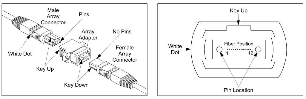
Figure 1: Basic Structure of MTP/MPO Connector

MTP/MPO Adapter

There are generally two types of MTP/MPO adapters according to the placement of the key.

Type A: Key-up to key-down: Here the key is up on one side and down on the other. The two connectors are connected turned 180° in relation to each other.

key-up-to-key-down-mtp-adapter 
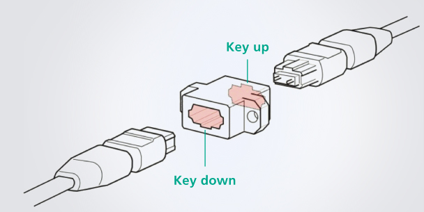
Figure 2: Key-up to Key-down (Type A) MTP/MPO Adapter

Type B: Key-up to key-up: Both keys are up. The two connectors are connected in the same position as the other.

key-up-to-key-up-mtp-adapter 
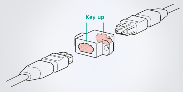
Figure 3: Key-up to Key-up (Type B) MTP/MPO Adapter

Fiber Patch Cords

Two types of duplex fiber patch cords are defined in the TIA standard: A-to-A (cross-over) Type and A-to-B (straight-through) type. Note: A-to-A patch cords are not commonly deployed and should be used only when necessary as part of a polarity method (See ANSI/TIA-568-C.0).

A-to-A and A-to-B fiber patch cord 
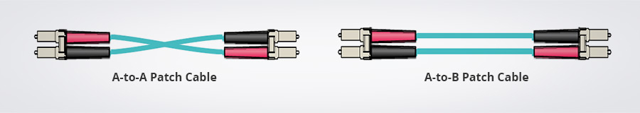
Figure 4: A-to-A and A-to-B Fiber Patch Cords

MTP/MPO Cassette

A cassette is a packaged, pre-terminated cabling assembly that transitions from multi-fiber cables and array connectors to traditional single-fiber connectors. These cassettes are usually fitted with 12-fiber or 24-fiber MTP/MPO adapter, and have LC or SC adapters on the front while MTP/MPO at the rear. The adapter mounted at the rear of a cassette defines it as either Method A or Method B MTP/MPO modular cassette. Method A MTP/MPO cassette makes a “key up to key down” connection between the internal MTP connector and the MTP array cable connector. Method B MTP/MPO cassette makes a “key up to key up” connection.

mtp-lc-modular-cassette 
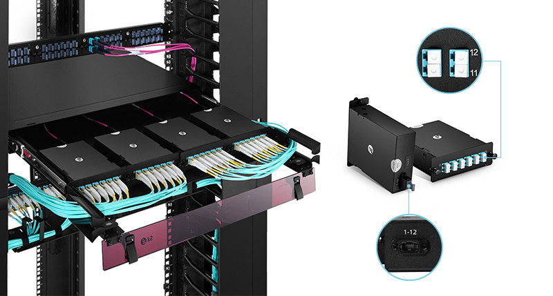
Figure 5: MTP/MPO-LC Modular Cassette

Note: Method A cassette works for both single-mode and multimode channels, while there is a limitation of Method B cassette: it doesn’t allow the use of an angled polished (APC) single-mode connector.

MTP/MPO Trunk Cables

There are three different MTP/MPO array patch cords defined in the TIA standard. The three different cables: Type A, B and C are used for the three different connectivity Methods A, B and C respectively.

three-types-mtp-mpo-trunk-cables 
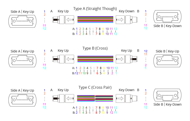
Figure 6: Three Types of MTP/MPO Cable

Ensure Right MTP/MPO Polarity System

As stated above, proper polarity demands that every transmit signal (Tx) goes to the receiving equipment (Rx). Then how to use these MTP/MPO trunk cables, fiber patch cords and MTP/MPO cassettes to ensure correct MTP/MPO polarity system? The following picture summaries the common rules to connect the components for the three types of MTP/MPO trunks.

rules-of-maintaining-right-polarity 
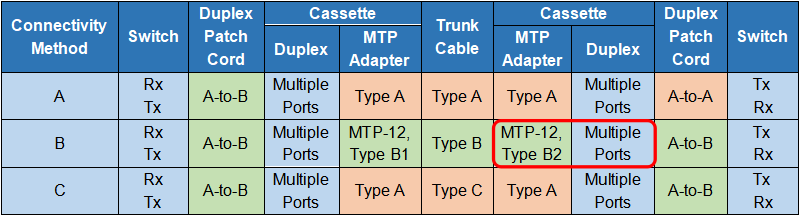
Figure 7: Rules for Maintaining Right Polarity

According to the chart, we can easily figure out that:

 Connectivity Method A is the most straight forward one, yet it needs a A-to-A patch cable at one end.  Connectivity Method B uses A-to-B patch cables at both ends, but the cassettes must be flipped over at one end so that the fiber originated in position 1 mapped to position 12.  Connectivity Method C is a variant of Method A, but with the cross-over happened in the trunk cable. So it also uses A-to-B patch cable at both sides.

Note: No matter which method is selected, there must be a pair-wise flipping (A-to-B polarity swap) that takes place at some point in the link. If the pair-wise flipping does not occur in the cassette then the pair-wise flipping must occur in the duplex patch cord or the MTP trunk cable and/or adapters.

FS Streamlined Polarity Solution for Serial Duplex Signals

For base-8/base-12/base-24 structured cabling, we have our own polarity solutions. You can also refer to our white paper Understanding Fiber Polarity for details.

Base-8 Polarity Solution

Base-8 infrastructure requires Type B components to maintain the correct polarity scheme. Base-8 MTP/MPO is SR4 and PLR4 ready, meaning that the backbone connectivity has the same fiber count as the SR4 and PLR4 transceivers. Please note although SR4 and PLR4 are 8 fiber interfaces, the Base-12 MTP/MPO connector is still compatible with them.

Base-12 Polarity Solution

Each 12-fiber MTP/MPO translates into six 2-fiber serial optical circuits that require polarity management that can be achieved using one of numerous methods.

Method A

The TIA-568-C.0 standard Method A, as we have mentioned above, uses a single module type (Type A cassette) wired in a “straight-through” configuration and two different patch cords in an optical circuit. With FS Type A and Type AF cassette, you no longer need the A-to-A patch cable. The recommended A-to-B patch cable can be used in both ends.

12-fiber method A polarity 
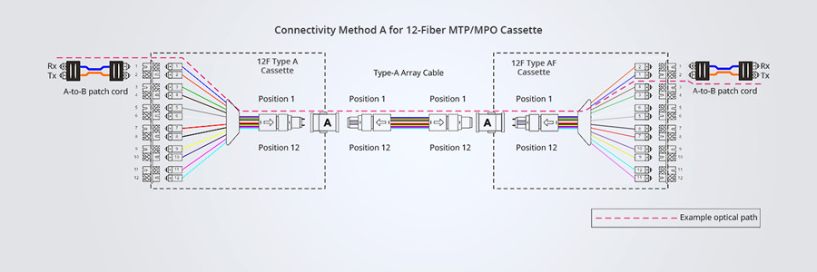
Figure 8: Method A Connectivity

Method B

Standard Method B employs key up to key up adapters to link straight-through key up to key up trunk cables to fiber cassettes. The fiber channel is completed by flipping the second cassette. The standard Method B flips the second cassette by rotating it 180 degrees and re-numbering it. While FS Method B does so by inversing the entire numbered LC adapters on the cassettes. The Type B1 cassette used in the link is the same as standard Type B cassette, and the Type B2 cassette is re-designed with adapters numbered in different sequence. A-to-B patch cables are still adopted at the beginning and end of the link.

12-strand method B polarity 
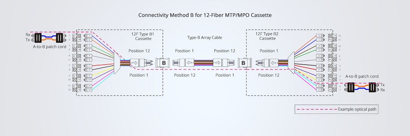
Figure 9: Method B Connectivity

Method C

FS Method C has nothing different from the standard Method C – both employ key up to key down adapters to link a special key up to key down trunk cable to Method A cassettes. Polarity is achieved by using Type C MTP/MPO trunks that has the pair-wise flip built in to individual fiber pairs, and the fiber channel is completed by utilizing A-to-B patch cables at both ends of the link.

12-fiber method C polarity 
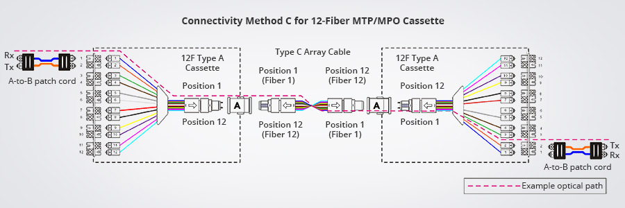
Figure 10: Method C Connectivity

Base-24 Polarity Solution

To catch up with the increased demand for higher bandwidth, 24-fiber MTP/MPO cable is introduced to facilitate migration to 100G network. It doubles the density of 12-fiber cabling in the same footprint, which reduces the fiber count, allows for fewer cable pathway, and improving airflow. The polarity maintenance of base-24 MTP/MPO cabling, however, is more complicated. FS recommends the Type A (key-up to key-down) MTP/MPO trunk cable. With our Type A and Type AF cassette, no need for A-to-A patch cable any more. The connectivity method is illustrated in the following picture.

24-fiber method C polarity 
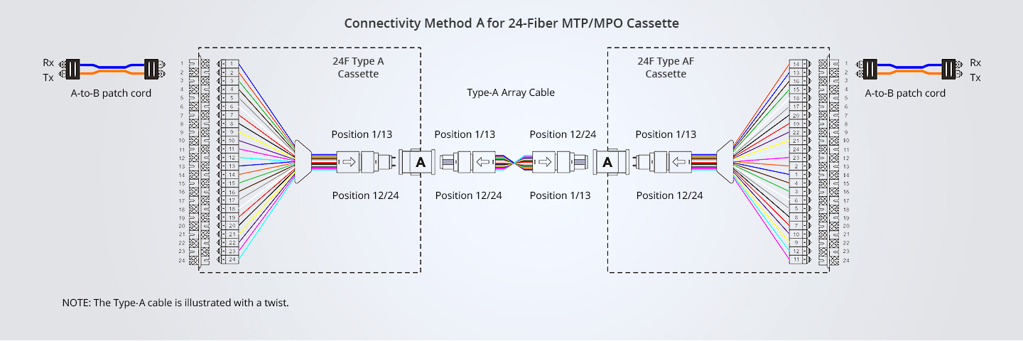
Figure 11: Method A Connectivity for Base-24 MTP/MPO Cabling

FS Polarity Solution for 12-Fiber Parallel Signals

The following table illustrates the corresponding connectivity methods A, B and C to establish polarity for parallel signals using an MTP transceiver interface with one row of fibers. Compared with polarity methods for duplex signals, there are two differences for parallel signals. First, the MTP/MPO cassettes for duplex signals are replaced with MTP-to-MTP adapters for parallel signals. Second, the duplex fiber patch cords for duplex signals are replaced with 12-fiber patch cords for parallel signals.

polarity for 12-fiber parallel signals 
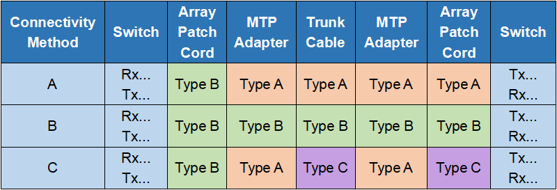
Figure 12: Polarity Methods A, B, C for Parallel Signals

Method A

When connecting arrays for parallel signals, the Type-A backbone (composed of one or many Type-A array connector cables mated in Type-A adapters) is connected on each end to a patch panel. On one end of the optical link, a Type-A array patch cord is used to connect patch panel ports to their respective parallel transceiver ports. On the other end of the optical link, a Type-B array patch cord is used to connect panel ports to their respective parallel transceiver ports. In each optical path there shall be only one Type-B array patch cord.

method A connectivity for parallel signal 
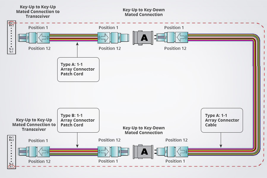
Figure 13: Connectivity Method A for Parallel Signals

Method B

When connecting parallel signals, the Type-B backbone (composed of one or many Type-B array connector cables mated in Type-B adapters) is connected on each end to a patch panel. Type-B array patch cords are then used to connect the patch panel ports to their respective parallel transceiver ports.

method B connectivity for parallel signal 
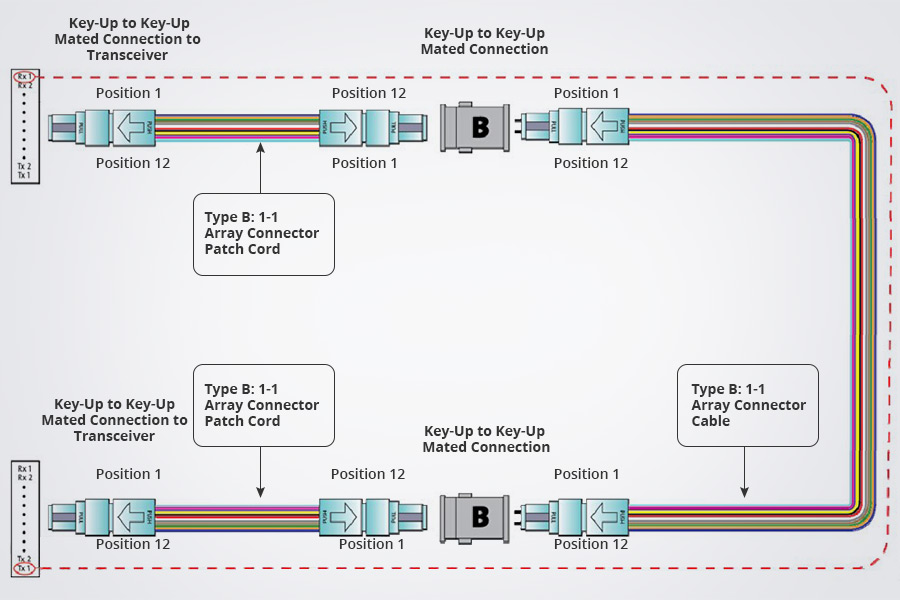
Figure 14: Connectivity Method B for Parallel Signals

Method C

Connectivity Method C for parallel signals is similar to connectivity Method A. The differences are Type C trunk cable is used instead of Type A, and a Type C cross-over patch cord is required at one end and at the other end, still Type B patch cable used.

method C connectivity for parallel signal 
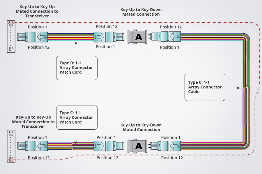
Figure 15: Connectivity Method C for Parallel Signals

Conclusion

Data centers are at the heart of the tremendous amount of business data needing to be transmitted, processed and stored. Thus fiber optic links are vital for providing the bandwidth and speed needed to transmit these data. Today’s enterprise business are embracing the trend of 40/100G and seeking the most effective method to migrate to higher speed – they leverages MTP/MPO components to satisfy the requirement. The polarity issues of MTP/MPO cabling can be solved by selecting the right types of MTP/MPO cables, MTP/MPO connectors, MTP/MPO cassette and patch cables. FS polarity management solution for base-12 and base-24 MTP/MPO cabling allows data center managers to effectively migrate to 40/100G. For more details, please visit www.fs.com.


You might be interested in

Knowledge
Knowledge
Knowledge
See profile for Sheldon.
Sheldon
Decoding OLT, ONU, ONT, and ODN in PON Network
Mar 14, 2023
384.8k
Knowledge
See profile for Irving.
Irving
What's the Difference? Hub vs Switch vs Router
Dec 17, 2021
367.0k
Knowledge
See profile for Sheldon.
Sheldon
What Is SFP Port of Gigabit Switch?
Jan 6, 2023
334.3k
Knowledge
See profile for Migelle.
Migelle
PoE vs PoE+ vs PoE++ Switch: How to Choose?
Mar 16, 2023
419.8k
Knowledge
Knowledge
Knowledge
Knowledge
See profile for Moris.
Moris
How Much Do You Know About Power Cord Types?
Sep 29, 2021
293.5k