How to Connect Multiple Ethernet Switches
Normally, we combine several Ethernet switches together to meet our needs (port number, certain functions, etc.) when one switch can't. Then how to connect multiple Ethernet switches in networking? In general, there are three main technologies: switch cascade, switch stack and switch cluster. This article aims to elaborate on three technologies and the best way among them in switch to switch connection.
Connect Multiple Ethernet Switches by Switch Cascade
Cascading switch is a traditional way to connect multiple Ethernet switches, which comes with various methods involving diverse network topologies. By cascading more than one switch together, users can have multiple ports interconnecting each of the switches, all of which can be configured and managed independently in the group. Among the switch cascade network, daisy chain topology and star topology are two common ways.
Daisy Chain Topology – Daisy Chain Switches One by One
Daisy chain topology, as its name implies, connects each switch in series to the next like the petals of a daisy. It is the simplest way to add more switches in a network. The structure of daisy chain network switches can be linear (where the switches at both ends are not connected, figure 1) which can be simply described as A-B-C, or circular (where the switches at both ends are not connected, figure 2) which can be simply described as A-B-C-D-E-F-A.

Figure 1: daisy chain switches via linear topology
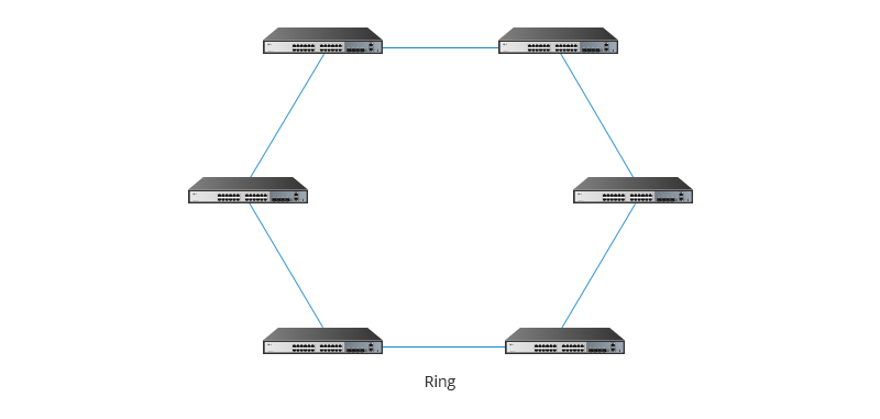
Figure 2: daisy chain switches via ring topology
For no more than three Ethernet switches, a linear topology of daisy chaining is okay since there is no loop. However, it owns drawbacks in switch failure due to lacking redundancy. In linear topology, data must be transmitted from one switch to another in one direction. Once one network switch fails, the others will also be dragged in. In general, linear daisy chain networks are less flexible, similar to electrical series circuits, where one interruption affects other connected items.
For more than three Ethernet switches, ring topology is better. It allows two-way transmission where data is sent in both directions. If the ring breaks at a particular link then the transmission can be sent via the reverse path, thereby ensuring that all switches are always connected in the case of a single failure. However, in ring topology, daisy chaining switches are inevitable to cause loop that can create broadcast storms and network congestion. So you’d better make sure your network switch support STP (Spanning Tree Protocol) to deal with the loop issue.
Star Topology – Link Access Switches to the Core
In a star topology, all the switches in a network are connected to a core switch through point to point link. In this way, information is transmitted from the central switch to the destination node, with any communication between two switches in a star network controlled by a central one. Star topology is widely used in connecting several gigabit switches together.
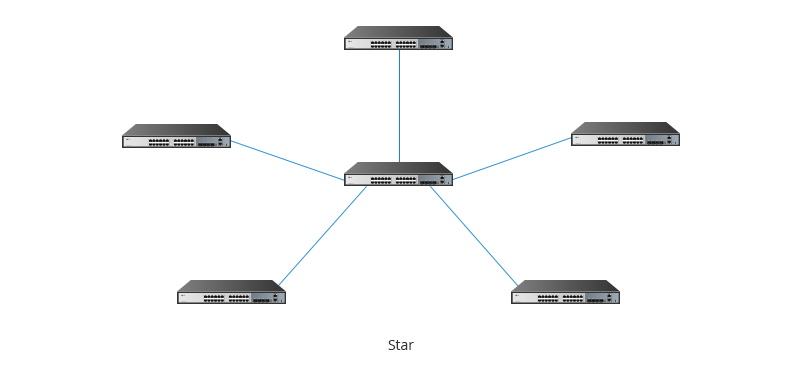
Figure 3: link access switches to the core to form star topology
When connecting Gigabit switches through star topology, a powerful switch (such as 40G switch) often acts as the core, which then connects to the access switches (such as 10G switches). In this scenario, no loop occurs and all access switches are much closer to the central switch.
Connect Multiple Ethernet Switches by Switch Stack
Switch stack is to combine multiple switches to make them work together for the purpose of providing as many ports as possible. Multiple switches are stacked to form a stack unit. And When stacking multiple switches together, the port density of a stack unit is the sum of the combined ports, greatly increasing the network connectivity. For example, stack two S3900-24T4S stackable Gigabit switch together, which then can provide 48 1GbE port density and nearly get twice switching capacity on the basis of one single switch stack. Usually, S3900 series switches can support up to 6 switches stacked together.

Figure 4: six S3900-24T4s switches stacking together
Connect Multiple Ethernet Switches by Switch Cluster
Switch cluster can manage the multiple interconnected switches as a single logical device. Switch cascade and stack are prerequisites for cluster. In a cluster, there is usually only one administrative switch, called a command switch, which can manage other switches. In a network, these switches require just one IP address only for the command switch, which saves valuable IP addresses resources.
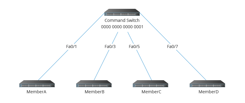
Figure 5: a command switch and several member switches in a switch cluster unit
Which Is the Best Way to Connect Multiple Ethernet Switches?
Traditional cascading Ethernet switch (daisy-chain topology or star topology), as well as advanced switch stacking and switch clustering, are three ways to connect multiple network switches. Then which is the best? You need to know their differences first. The table below shows the differences among switch cascade vs switch stack vs switch cluster, which will give you a better understanding of their respective properties.
| Switch Cascading | Switch Stacking | Switch Clustering | |
|---|---|---|---|
| Number of Connected switches | No limitation in principle | Limited | Limited |
| Bandwidth | Won't be increased | The bandwidth is much increased | It depends on whether you adopt switch cascading for clustering or switch stacking for clustering, then the bandwidth of clustering unit equals that of the stacking unit or cascading unit |
| Operation & Control | Member switches are managed separately | Member switches are managed as a whole by master switch | Member switches are managed as a whole by command switch |
| Flexibility | Almost all the switches can be cascaded regardless of manufacture and types | Usually happens in stackable switches of same models from the same manufacturer | Only specific cluster-capable switches from the same manufacturer can be clustered. |
| IP Address Management | Each switch has one IP address | All the switches share a single IP address | Only one IP address for command switch |
From what is shown in the table, we can know that all of them have respective pros and cons. Therefore, how to connect multiple Ethernet switches should rely on your particular applications.
Related articles:
Uplink Port Vs. Normal Port: Can I Use Uplink Port as Normal Port?
You might be interested in
Email Address

-
PoE vs PoE+ vs PoE++ Switch: How to Choose?
May 30, 2024


