
Decoding Connectivity: A Fascinating Exploration of GPON Technology
PON (Passive optical network) technology was available in the middle of 90s. Since the huge development of network, various standards have been established and matured. PON developed from the first ATM PON (APON) and then evolved in Broadband PON (BPON) which is compatible with APON. Later, arisen Ethernet PON (EPON) and Gigabit PON (GPON) bring great improvement in data transmission distance and bandwidth. This tutorial will introduce about GPON technology.
GPON Components
GPON is defined by ITU-T recommendation series G.984. GPON represents an increase in bandwidth compared with APON and BPON. GPON network supports speeds of 1.244 Gbps upstream and 2.488 Gbps downstream. There are four main components in GPON network: the OLT, the transmitting media, the optical splitter, and the ONT/ONU.
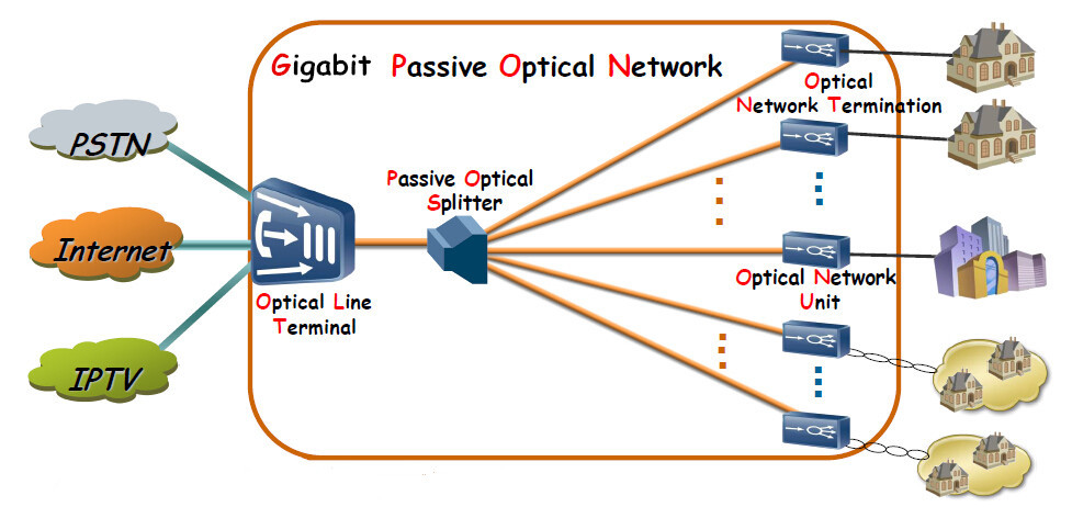
OLT
OLT, Optical Line Terminal, is a device which serves as the service provider endpoint of a passive optical network. It is an active Ethernet aggregation device that is usually located in a data center or the main equipment room. An OLT converts the optical signals transmitting over fiber to the electrical signals and presents them to a core Ethernet switch. The OLT replaces multiple layer 2 switches at distribution points. OLT distributing signal is connected with backbone cabling or horizontal cabling through optical splitters, which are connected to the optical network terminal at each work area outlet.

Transmitting Media
GPON transmits signals through the passive, physical cabling infrastructure. The transmitting media includes copper, fiber optic patch cords, enclosures, adapter panels, connectors, gpon fiber splitters and other materials. All these transmitting media components should be factored in the channel loss budget to get a better system performance.
ONT/ONU
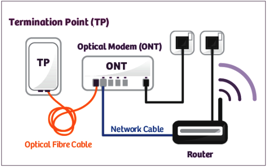
The user endpoint in a GPON system is represented by the Optical Network Termina (ONT), also referred to as Optical Network Unit (ONU). Functioning as a specialized modem, the ONT transforms optical signals into electrical signals directly at the user's location, facilitating broadband access for devices such as WiFi, TVs, desktops, and more. Moreover, the ONT efficiently sends aggregated data back to the OLT, ensuring seamless communication between the end-user and the network.
GPON Loss Budget
Table1. Loss budget for GPON system:
GPON Power Budget
The transmitter’s power and receiver’s sensitivity are two parameters that influence the reach of the access network. To calculate the power budget, the formula is 'P = FCA * L + SL + Penalties,' where P represents the power budget, FCA is the fiber cable attenuation in dB/m, L is the distance, and SL is a splitter loss. Penalties stand for additional losses such as splices and connectors. The following table shows the required power budget for different GPON configurations.
Table 2. Minimum power budget for different GPON configurations:
Conclusion
PON have evolved, with GPON defining a new standard for enhanced bandwidth. In GPON network, main components like the OLT, Transmitting media, optical splitters and ONT/ ONU play pivotal roles. Meanwhile, GPON loss and power budgets are crucial for optimal network design and reach.
You might be interested in


Email Address


PoE vs PoE+ vs PoE++ Switch: How to Choose?
May 30, 2024


-