Using MLAG in Data Center Network Design
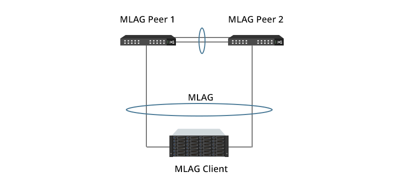
MLAG, or MC-LAG, stands for multi-chassis link aggregation group. It is a multi-device link aggregation technology that enables two switches to act as a single switch. The ports from different MLAG peer switches are bundled together to act as a single logical link, providing increased link bandwidth and extra redundancy.
Over the years, MLAG has been widely used as a virtualization technology in data center network design. This article elaborates on the key benefits of MLAG and its applications in different data center architectures.
MLAG in Data Center Network Design
In traditional data center networks, redundant devices and links are used to realize high resiliency and stability. However, it often leads to low link utilization and high network maintenance costs. Both MLAG and stacking technology can be used to solve such problems by virtualizing multiple data center switches into one switch, which simplifies network deployment and reduces maintenance expenses.
Compared with stacking, MLAG is considered to have higher reliability and shorter service interruption time. The figure below shows a typical MLAG topology used in data center network designs.

Key Benefits of MLAG
As an enhancement of link aggregation group (LAG), MLAG increases link bandwidth, improves link reliability, and eliminates port blocking and delays. The key benefits of using MLAG in data center architectures are listed below.
High Bandwidth & Resiliency
MLAG can simply bundle more links into the LAGs to increase bandwidth for North & South as well as East & West. It offers dual management and control planes, further improving resiliency. As control planes and fault domains are isolated, fault will not spread on peer switches.
Easy Upgrade
Two MLAG peer switches can be upgraded separately with simple operations and low risks. This prevents service interruption when either switch is upgrading.
Simplified Network
MLAG prevents loops on a Layer 2 network without deploying spanning tree protocol configuration. Thus, it greatly simplifies the data center network. Besides, it can add node-level redundancy to the normal link-level redundancy that a LAG provides.
MLAG Deployment Schemes
MLAG can be used in different data center architectures to eliminate bottlenecks and improve resiliency.
3-Tier Date Center Architecture
In a traditional 3-tier data center architecture, a peer-link is configured between two MLAG switches at the access or aggregation layer to exchange MLAG packets and forward traffic between them.
Because MLAG peer switches are two independent devices, they can serve as independent OSPF nodes, and be managed by independent NMSs. Moreover, MLAG supports preferential forwarding of local traffic, which minimizes east-to-west traffic between the MLAG peer switches. Dual-active detection (DAD), supported by MLAG, can also be realized without requiring additional cabling.
Access Layer
The following shows a scenario where MLAG is deployed on access switches. In this case, a server is dual-homed to two access switches with two NICs working in active-active mode. The two NICs on the server use the same MAC address and implement load balancing based on flow. Therefore, the ports connected to the server are configured as Eth-Trunk through MLAG. Both the MAC address and ARP entries of the two ports are synchronized.

Aggregation Layer
When MLAG is deployed on aggregation switches, it can enable a loop-free logical network between aggregation and access switches, which is not possible with STP. Two aggregation switches are paired, and the horizontal link between them is configured as peer-link. The ports of the two aggregation switches downstream connected to the same access switch are configured as cross-frame Eth-Trunk.

2-Tier Spine-Leaf Architecture
MLAG can also be applied to a 2-tier spine-leaf architecture. Two spine switches are paired as an MLAG domain. They can work as a single switch connected to the leaf switches. All links in the topology are used for forwarding with no blocked ports. The spine switches can act as the Inter-VLAN gateway for the data center VLANs.
The figure shows a typical deployment of MLAG in a 2-tier spine-leaf design.

At the leaf layer, NIC bonding or standard Link Aggregation is used to connect servers with multiple interfaces to leaf switches. As the two leaf switches are an MLAG pair, connections between servers and leaf switches are active-active redundant.
At the spine layer, two FS data center switches can also form an MLAG pair. They aggregate all of the uplinks in the architecture, which eliminates blocked ports and enables interconnect bandwidth on all ports.
High level of network bandwidth and performance is crucial to any data center design. Deploying MLAG in both traditional 3-tier designs and 2-tier spine-leaf designs help deliver system level redundancy and improve network reliability as well as scalability of data centers.
You might be interested in
Email Address

-
PoE vs PoE+ vs PoE++ Switch: How to Choose?
May 30, 2024


