WDM Basics: Understanding Wavelength Division Multiplexing Technology
Wavelength division multiplexing (WDM), known as the classic technology that provides optimal solutions for transporting large amounts of data between sites. With the endless upgrades and improvements, WDM technology is no longer just adopted by carriers and service providers, but also applied for enterprises, organizations, and data centers, meeting the demands for both public and private network uses. So, what is WDM? What benefits will WDM networking bring to the users? How about the applications of WDM? This WDM tutorial will explain all your inquiries.
Scenario Intro
Suppose there is a building on one side of a district that requires eight 10G fiber connections to a central office located several kilometers away. There are two potential solutions to this requirement.
Option 1: connect all of the fibers to the switch in the central office several kilometers away. Running 8 pairs of fiber all the way across the district will be an extremely expensive proposition at the risk of fiber breakage at the same time.

Figure 1 : Without WDM: Connection Between Central Office and Building
Option 2: Adding WDM Mux and Demux and only requiring one pair of fibers to conduct and realize the transmission, this solution saves fiber resources substantially and offers a more cost-effective and reliable alternative compared with the abovementioned one obviously. How to achieve this? With the aid of WDM technology.
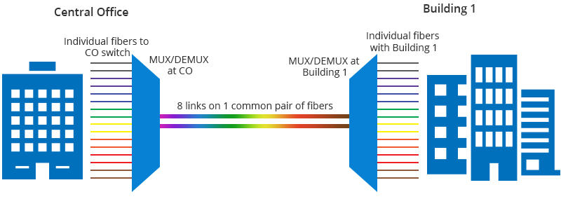
Figure 2 : With WDM: Connection Between Central Office and Building
What Is WDM (Wavelength Division Multiplexing)?
Briefly speaking, WDM is a technique in fiber optic transmission for using multiple light wavelengths to send data over the same medium. Specifically speaking, this technology multiplexes a number of optical carrier signals onto a single optical fiber by using different optical wavelengths (i.e., colors) of laser light. Every wavelength carries an individual signal that does not interfere with the other wavelengths. The diagram below illustrates the working principle of WDM technology.
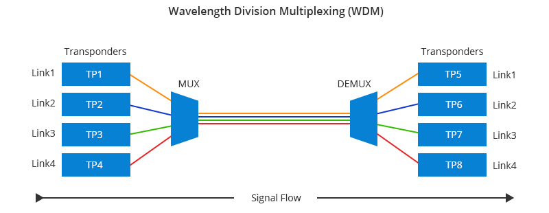
Figure 3 : Working Principle of WDM
Benefits of Adopting WDM Technology
Using WDM fiber brings several advantages, including:
-
Ultra-large Capacity Transmission: WDM is capable to transmit and receive high capacity data, which is a ready-made option for high-bandwidth transmission like 100G, 400G.
-
Ultra-long Distance Transmission: EDFA (Erbium Doped Fiber Amplifier) is often adopted in the WDM system, which will help to further boost the intensity of optical signals for long-range transmission.
-
Transparent Transmission: Due to the physical properties of light, all the wavelengths are independent since the channels don't interfere with each other to ensure transmission transparency. Adopting the optoelectronic devices will help to guarantee the reliability of the WDM system.
-
Flexible and Resilient Expansion: WDM technology allows new channels to be added as needed without disrupting existing services, simplifying upgrades. Today's DWDM ROADM platforms support deployment in various topologies, including point-to-point, linear chain, and ring. They also enable resilient mesh topologies with multiple protection mechanisms, ensuring both flexibility and reliability in optical transport systems.
-
Simplified Operations: Today's WDM networks offer integrated management solutions that greatly enhance operational efficiency. Combining DWDM with ROADM technology allows for rapid, dynamic provisioning of high-bandwidth services, reducing deployment times from months to days. Additionally, staff can remotely identify and resolve issues more quickly and effectively.
WDM Classifications: CWDM vs DWDM
What Is CWDM?
CWDM (Coarse Wavelength Division Multiplexing) is defined by wavelengths, which belongs to the ITU (International Telecommunication Union) in ITU-T G.694.2 spectral grids. It uses the wavelengths from 1270 nm to 1610 nm within a 20nm channel spacing. CWDM supports fewer channels than DWDM, which makes it the ideal solution for short-range communications as it's compact and cost-effective.
What Is DWDM?
DWDM (Dense Wavelength Division Multiplexing) is defined by frequencies, which belongs to ITU-T G.694.1 spectral grids. In practice, DWDM frequency is usually converted to wavelength. DWDM typically has the capability to transport up to 80 channels (wavelengths) in what is known as the Conventional band (C-band) spectrum, with all 80 channels in the 1550 nm region. Allowing huge amounts of data to travel in one single network link, DWDM is ideal for long-haul transmission as the wavelengths are tightly packed together.
The differences between CWDM vs DWDM lie in channel spacing, transmission distance, modulation laser, costs, etc., which has reflected in their practical applications.
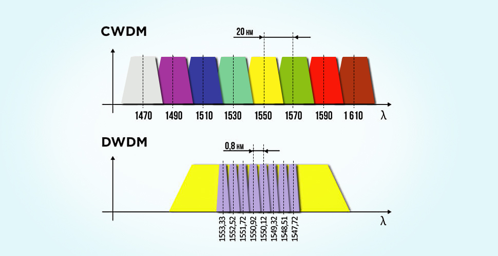
Figure 4 : WDM Diagram
WDM Systems: Single Fiber vs Dual Fiber
Single Fiber Transmission
Single fiber transmission method, namely, is a kind of bi-directional communication over one single fiber. This system utilizes two identical sets of wavelengths for both directions over a single fiber. Individual channels residing on the single fiber system may propagate in either direction.
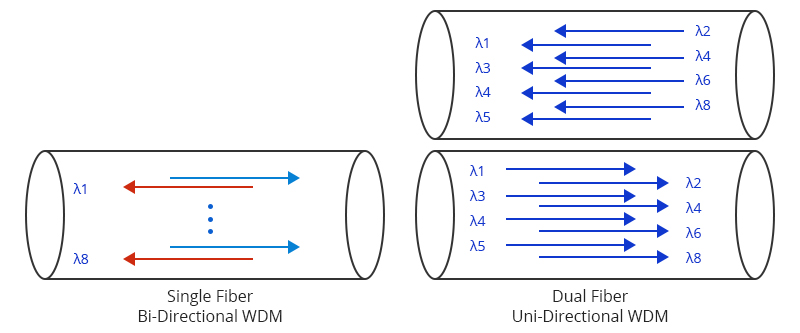
Figure 5 : Single Fiber Bi-Directional WDM & Dual Fiber Uni-Directional WDM
Dual Fiber Transmission
The dual fiber transmission method is comprised of two single fibers—one fiber is used for the transmit direction and the other is used for the receive direction. In a dual fiber transmission system, the same wavelength is normally used in both the transmit and receive directions. The second fiber may serve as a backup fiber as in a redundant system, or it may provide an optical path in the opposite direction.
Common WDM System Components
WDM fiber is a crucial element in the implementation of WDM technology. In a basic WDM system, there are four main components: Mux and Demux, transceivers, patch cords, and dark fiber. The sketch below illustrates a basic WDM structure:
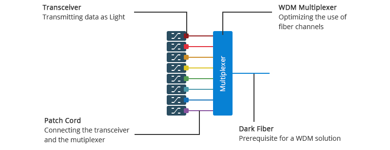
Figure 6 : Basic WDM Structure Diagram
Mux and Demux
WDM Mux and Demux is the key to optimize the use of the fiber. At the heart of the operation, the WDM multiplexer gathers all the data streams together to be transported simultaneously over a single fiber. At the other end of the fiber, the streams are demultiplexed, i.e. separated into different channels again. It's crucial to understand the Mux ports on a WDM Mux/Demux. Must-have ports are twofold: channel port & line port; functioning ports are basically covering expansion port, 1310nm port and 1550nm port, monitor port, etc. Understand Mux Ports On CWDM and DWDM Mux Demux will illustrate the different ports for you clearly.
Transceiver
The optical transceivers adopted in the WDM system are wavelength-specific lasers, corresponding to the CWDM and DWDM bands, which differ from the common modules with 850nm, 1310nm, 1550nm bands. It converts data signals from switches to optical signals that can be transmitted into the fiber. Each data stream is converted into a signal with a light wavelength that is a unique color.
Patch Cord
Briefly speaking, the fiber patch cable functions as the glue that joins the previous optical modules and multiplexers together to realize the transmission—connecting the output of the transceiver to the input on the multiplexer.
Dark Fiber
A prerequisite for any WDM solution is access to a dark fiber network. Adopting a fiber pair is considered as the common way to transport optical traffic. One of the fibers is used for transmitting the data and the other is used for receiving the data, which allows the maximum amount of traffic to be transported.
Additionally, optical add-drop multiplexer (OADM), optical amplifiers, EDFAs, DCMs, transponders may all be adopted to realize connectivity in some typical WDM topologies.
Typical WDM Topologies
Point-to-Point Topology
Point-to-point topology, typically in long-range transport, can be implemented with or without OADM. This kind of P2P topology is characterized by high channel speeds, high signal integrity and reliability, and fast path restoration. A WDM point-to-point system normally includes lasers, optical multiplexers and demultiplexers, fibers, optical amplifiers, and optical add-drop multiplexers. In long-haul networks, the distance between transmitter and receiver can be several hundred kilometers, and the number of amplifiers required between endpoints is typically less than 10. In the MAN, amplifiers are often not needed.
Ring Topology
Ring topology, typically in metropolitan areas, can span a few tens of kilometers. A ring configuration may cover one hub station and one or more OADM nodes. At the hub node, where the traffic originates, the traffic is terminated and connected with other networks. At the OADM nodes, the selected wavelengths are dropped and added, while the others pass through transparently. The ring architecture allows nodes on the ring to provide access to network elements such as routers, switches, or servers by adding or dropping wavelength channels in the optical domain. With an increase in the number of OADMs, however, the signal is subject to lose and amplification will be required.
Mesh Topology
Mesh architecture seems to be the future of optical networks because it is considered as a robust topology. By beginning with point-to-point links, equipped with OADM nodes at the outset for flexibility, and subsequently interconnecting them, the network can evolve into a mesh without a complete redesign. Additionally, mesh and ring topologies can be joined by point-to-point links.
Actually, different WDM topologies can be deployed in different scenarios. Point-to-point topologies might be used for connecting enterprise locations, ring topologies might be more suitable for connecting inter-office facilities (IOFs) or for residential access, and mesh topologies might fit for inter-POP connections and connections to the long-haul backbone. In practice, there also exists hybrid network topology that consists of mesh and/or rings that are interconnected with point-to-point links.
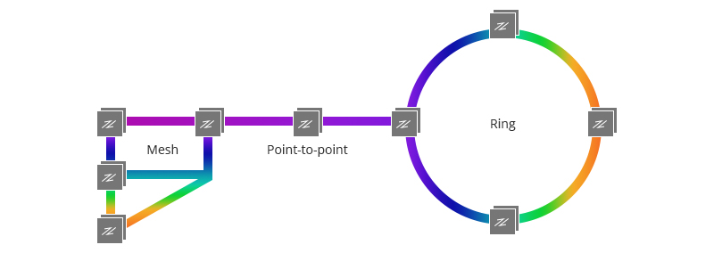
Figure 7 : Mesh Topology Diagram
Current Applications of WDM Technology
WDM technology not only witnesses the changes and improvements in optical transmission but also gets involved in the revolution, which has been reflected in the deployment of OTN (Optical Transport Network). Based on WDM technology, OTN with ultra-huge transmission capacity has added SDH (Synchronous Digital Hierarchy) technology to realize powerful functionalities of operation, maintenance, and management. OTN networks with WDM technology have been widely deployed in various scenarios, especially for long-haul and metro networks, which helps to optimize the links in the system and guarantee high-reliability networks.
FS 1.6T High Capacity OTN Solution
The FS 1.6T Data Center High-Capacity OTN Solution utilizes DWDM technology to achieve high-density, high-capacity data transmission. It offers 8 x 200G CFP2 interfaces on the line side and 16 x 100G QSFP28 interfaces on the client side, paired with an 8-channel DWDM MUX/DEMUX, enabling a total transmission capacity of 1.6T. DWDM multiplexes multiple wavelengths onto a single fiber, significantly enhancing fiber utilization and reducing hardware costs. Erbium-Doped Fiber Amplifiers (EDFAs) boost optical signal strength for ultra-long-distance transmission. The solution features 1+1 hot-swappable power supplies and 2+1 intelligent cooling fans for high reliability and efficiency. Its plug-and-play design simplifies operations and allows for easy upgrades, ensuring improved data transmission efficiency, flexibility, and reliability for data centers.
Conclusion
In conclusion, the construction of large-scale optical transmission networks, such as 100G OTN backbone networks, is progressing. The industry is accelerating R&D and the industrialization of ultra-high-speed transmission technologies like 400G, 800G, and 1T, aiming for significant advancements in optical transmission. This will further expand WDM technology applications in networking. The optical transmission network equipment ecosystem is becoming more comprehensive, with increased adoption of WDM and optical access equipment worldwide. Consequently, the optical transmission industry is expanding, and the demand for WDM applications is expected to grow significantly. WDM technology is crucial for accelerating the development of OTN networks towards higher speeds, larger capacities, lower costs, and more intelligent, environmentally-friendly solutions in the future.
Appendix: WDM Glossary of Terminologies
-
TDM: The abbreviation for "Time Division Multiplexing," an alternative to WDM. Instead of multiple channel wavelengths, TDM protocols define multiple time-slots in which different channels occupy each at the same wavelength.
-
Wavelength: Refers to the distance between two points of the same phase in consecutive cycles of a wave, measured in the direction of propagation. The wavelength λm of monochromatic light traveling in an optical fiber is expressed:
λm = λ / n = v / f
λ = optical wavelength in a vacuum
n = the refractive index of the dielectric medium
v = phase velocity, given by c / n
c = the speed of light in a vacuum: 2.99792458 X 10⁸ m/s
f = the optical frequency
-
Channel: In WDM systems, each input channel is assigned a unique wavelength (i.e. color of light), thus the channels can traverse the fiber "in parallel."
-
Circuit: Sometimes used to identify a group of WDM wavelengths that are combined and associated with a single fiber path or span. Ports on the WDM products will be labeled to identify the circuit associated with that port.
-
Add/Drop: The add/drop terminology may refer to a single wavelength filter, or to a multi-channel WDM product. In the case of the filter, it is just another way to describe the bi-directional nature of the filter, in which a particular channel wavelength may be either added as in multiplexed; or dropped as in de-multiplexed.
-
Insertion Loss/Return Loss: Insertion loss is the attenuation caused by the insertion of WDM filter in an optical transmission system; return loss is the loss of power in the signal returned/reflected by a discontinuity in a transmission line or optical fiber of WDM systems.
-
Polarization Dependent Loss (PDL): The loss exhibited by a WDM filter is dependent on the optical polarization of the light. PDL is the largest difference in maximum insertion loss occurring at all states of optical polarization.
You might be interested in
Email Address

-
PoE vs PoE+ vs PoE++ Switch: How to Choose?
May 30, 2024


